
About
📅 26 September 2026 · ✍️ Jwell Technical Team — Geomembrane Extrusion Engineering · ⏱️ ~15 min read
HDPE geomembrane (high-density polyethylene geomembrane) is the workhorse anti-seepage material for landfills, wastewater treatment lagoons, artificial lakes, aquaculture ponds, mine tailings facilities, chemical containment and hydraulic engineering.
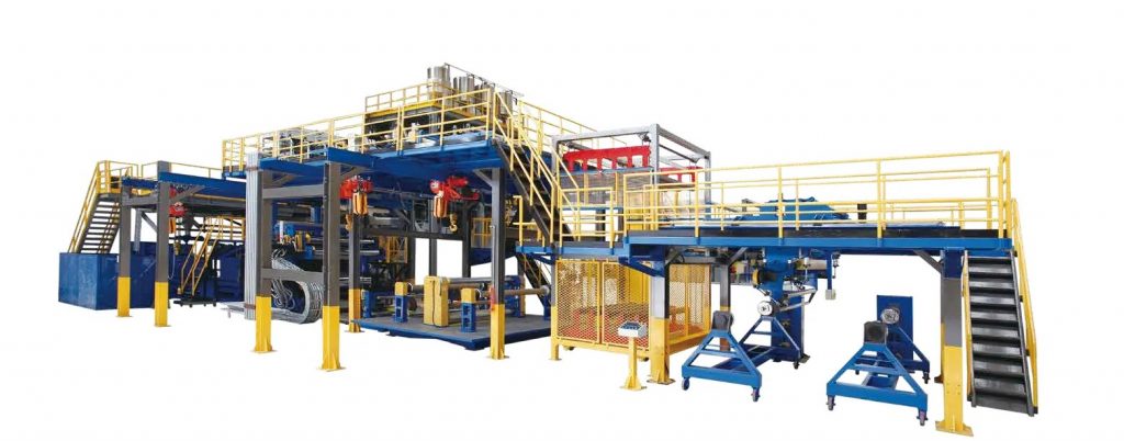
For any containment project, the material properties of the HDPE geomembrane itself are only the foundation. Subgrade quality, panel deployment, thermal welding, detail treatment and seam testing have an equally direct impact on the final anti-seepage performance.
HDPE geomembrane installation therefore follows the sequence:
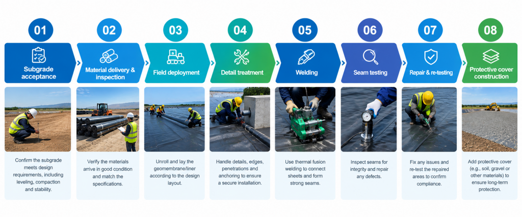
Subgrade acceptance → Material delivery & inspection → Field deployment → Detail treatment → Welding → Seam testing → Repair & re-testing → Protective cover construction
…with specific construction parameters governed by the project design documents, applicable construction specifications and works classification. This guide walks through the 8 critical steps from site preparation to final acceptance, written for contractors, EPC firms, supervisors, procurement engineers and asset owners.Standards note: In China, HDPE geomembrane products are governed by GB/T 17643-2025 (Geosynthetics — Polyethylene geomembrane). Installation must additionally follow the project design documents and the applicable water conservancy, municipal, environmental, transport or building codes. International projects commonly reference GRI-GM13 (material), GRI-GM19 (seam QA) and ASTM D6392 (seam peel/shear testing). Always defer to the governing project specification.
HDPE geomembrane is produced from polyethylene resin with carbon black, antioxidants, anti-aging agents and UV stabilizers, by flat-die extrusion, cast or blown-film processes. In service it delivers four properties that make it the default liner choice:
HDPE has an extremely low liquid permeation rate and functions as a continuous barrier separating water, wastewater, leachate or other liquid media from the environment.
HDPE tolerates a wide range of acids, alkalis, salts and industrial chemical media — the reason it dominates wastewater, mining, chemical and solid-waste containment. Chemical compatibility must always be verified against the actual medium, concentration, temperature and exposure duration.
Unlike rigid barrier materials, HDPE geomembrane accommodates a degree of subgrade deformation and differential settlement, making it suitable for lagoon basins, slopes and landfill geometries.
HDPE sheets are joined by hot-wedge or extrusion fusion welding. With correctly controlled temperature, pressure and speed, seams become a homogeneous continuation of the liner — no adhesive, no mechanical seam. This is why material quality and welding quality must be controlled together.
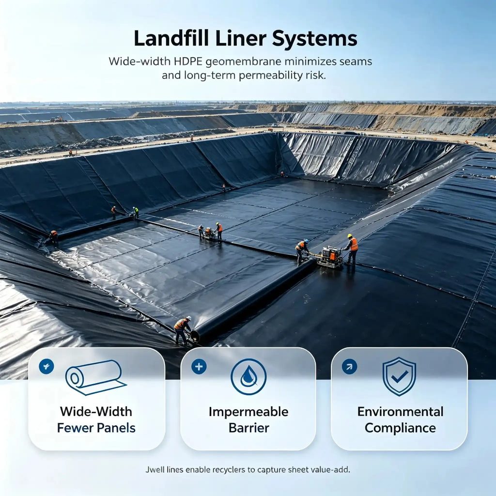
Municipal landfills · leachate treatment ponds · wastewater treatment lagoons · industrial effluent ponds · hazardous waste facilities · equalization basins · lined storage tanks
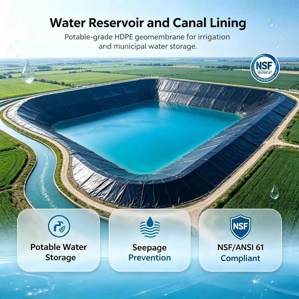
Reservoir lining · water storage ponds · river-channel seepage control · artificial lakes · canals · dam and levee anti-seepage · slope lining
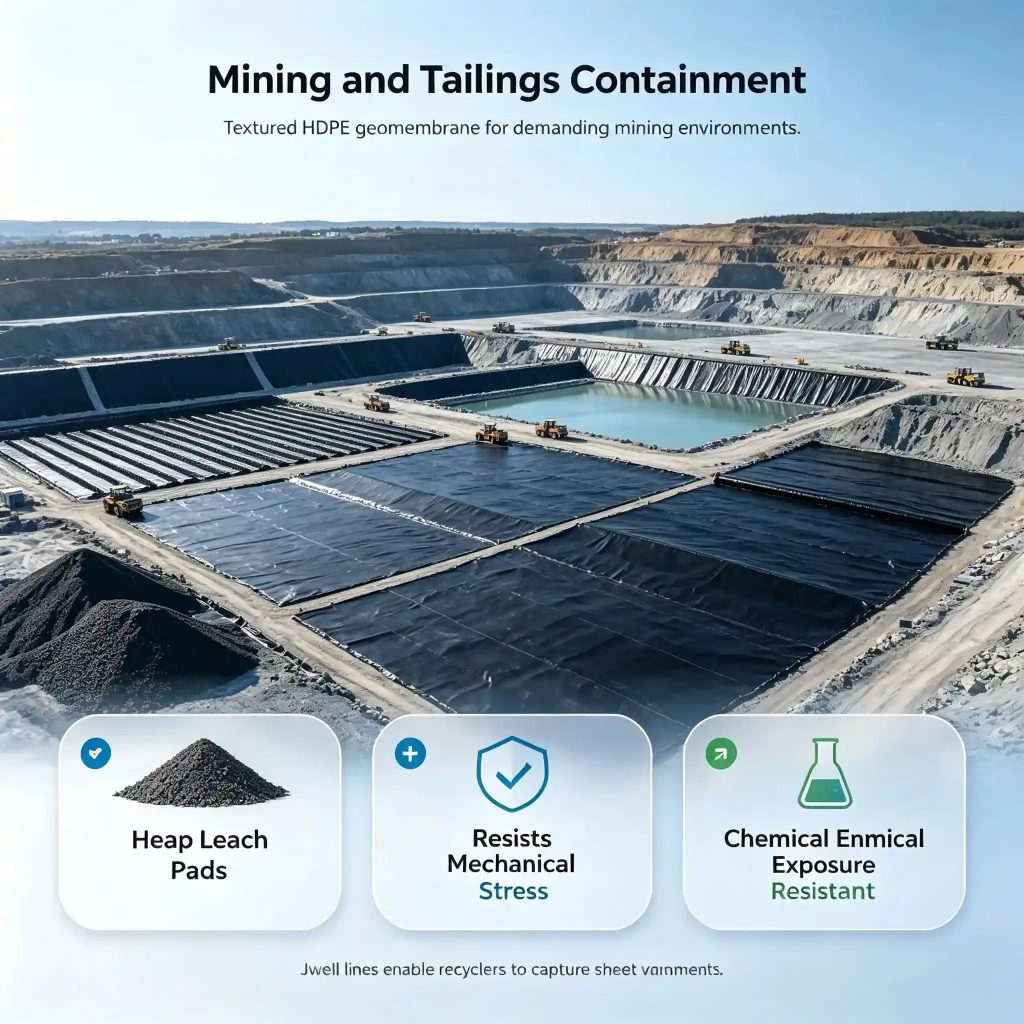
Tailings storage facilities · heap-leach pads · wash ponds · settling ponds · leachate ponds · process solution containment
Fish ponds · shrimp ponds · storage reservoirs · irrigation ponds · biogas digesters · oxidation ponds
Chemical storage basins · reaction ponds · settling ponds · tank-farm secondary containment · industrial wastewater · secondary containment liners
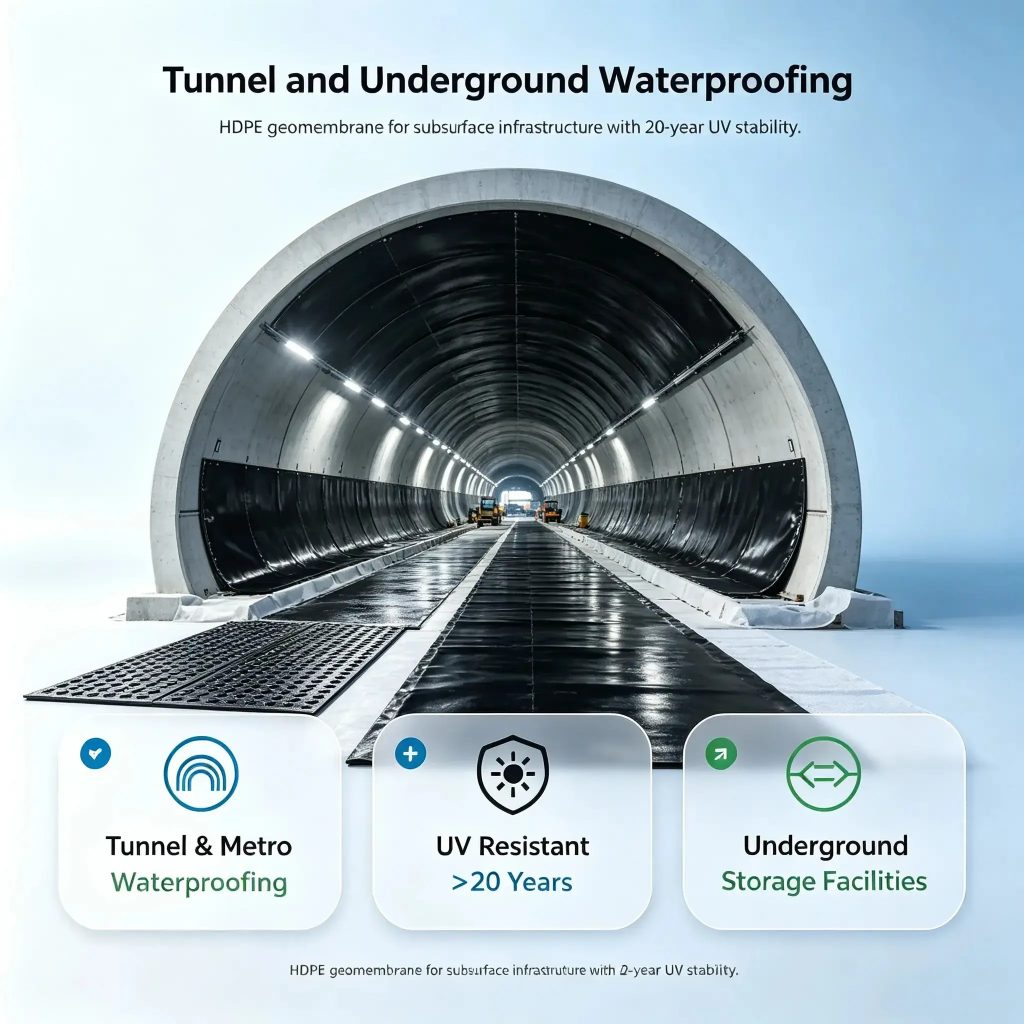
Underground works seepage control · metro construction · buried water tanks · roof water features · landscape water bodies · basement waterproofing isolation
Different applications impose different requirements on thickness, width, resin, environmental resistance and welding method — which is why liner specifications should be fixed against the final application at the production stage.
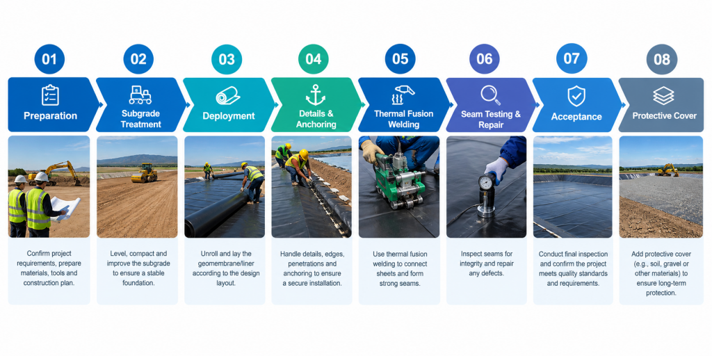
01 Preparation → 02 Subgrade treatment → 03 Deployment → 04 Details & anchoring → 05 Thermal fusion welding → 06 Seam testing & repair → 07 Acceptance → 08 Protective cover
Each step is inspected and accepted before the next begins — this sequencing is the single cheapest insurance against rework and leakage.
Complete drawing review and technical disclosure before mobilizing. Confirm: liner specification and thickness · deployment extent · anchoring method · overlap orientation · seam layout · pipe penetrations · inside/outside corners · movement-joint treatment · protective cover structure · drainage and diversion systems. On large projects, produce detailed panel layout drawings from site dimensions.
Run a nesting analysis across the basin floor, slopes and details before cutting anything. Good layout:
For large landfills, reservoirs and tailings facilities, establish a full panel-numbering and seam-numbering system before deployment.
The subgrade is one of the most important quality-control gates in the whole installation. Sharp stones, concrete rubble, roots or visible differential settlement under the liner create concentrated stress points — the classic cause of puncture and leakage.
Before deployment, inspect and clear the subgrade to satisfy:
Where a sand bedding or other cushion layer is specified, construct it per the design documents. After subgrade acceptance, keep personnel and machinery off the finished surface.
Deployment and welding need suitable temperature, wind and humidity. Avoid: high wind · rain or snow · wet membrane surface · extreme heat · extreme cold. The practical temperature window is set by the membrane grade, welder type, project specification and field trial-weld results.
Lay panels naturally flat against the subgrade — never stretch the liner taut, never leave it bridging. Correct slack accommodates thermal expansion/contraction and subgrade movement during welding and long-term service.
Adjust panel position continuously to eliminate irregular wrinkles. Focus inspection on slopes, corners, pipe penetrations, anchorage zones and panel intersections.
HDPE panels are large in area and light in weight — wind is a real hazard during deployment. Ballast with sandbags or other non-damaging temporary loads.
Complex details are where liner systems are won or lost.
Cut and reinforce per design. In stress-concentration zones, apply dedicated reinforcement patches, welded reliably to the parent liner.
The archetypal difficult detail. Fabricate purpose-made boots or patches to suit the pipe diameter and node structure, joined by fusion welding, extrusion welding or mechanical fixation. For HDPE pipes, compatible HDPE connection systems may be used per design.
Anchor dimensions, embedment depth and connection structure must follow the project design documents — a one-size-fits-all detail is never acceptable.
Welding is the core operation of the installation. The common methods:
Never run long production seams off "experience" parameters. Trial-weld against the actual: membrane thickness · HDPE resin behavior · ambient temperature · wind · membrane surface condition · welder model. The trial establishes the working combination of welding temperature + travel speed + pressure/clamping, verified by seam quality testing.
The overlap must be clean and dry. Remove dust, grit, moisture, oil and other contamination. If the surface is damp, dry it before welding.
During automatic welding, monitor continuously for: seam continuity · stable weld width · welder tracking on the seam line · no excessive thermal damage · no skipped weld · no intermittent (jump) welding · no cold (unfused) weld · no burn-through.
Machine parameters are not "set once, run all day." When ambient temperature, wind or membrane condition changes materially, re-trial and re-adjust.
Pressurize the inflation channel between the two weld tracks to the specified pressure and monitor the decay. Pressure behavior reveals any through-going discontinuity in the seam.
For extrusion welds, patches and complex details: apply soap solution over the seam, place the vacuum box, and observe. Continuous bubbling marks a defect for repair.
For special structures or where the design requires it, spark testing detects potential through-defects. Test voltage, dwell time and equipment must follow the applicable method and project specification.
Critical containment works require destructive seam sampling per design and specification. Tests typically cover peel performance, shear performance and seam strength. Sample locations must be numbered and logged. Holes left by sampling are repaired with certified HDPE patches and re-tested non-destructively.
Typical defects found in testing: skipped weld · cold weld · discontinuous seam · localized burn-through · insufficient seam width · mechanical damage · holes · through-defects.
After repair, do not rely on visual inspection alone — re-run the appropriate non-destructive test for the defect type. Every repair must be logged with: defect number · repair location · repair time · repairer · test result.
A complete HDPE geomembrane works file includes: design documents · material certificates · material test reports · incoming inspection records · subgrade acceptance records · deployment records · welding logs · trial-weld records · seam test records · destructive test reports · repair records · concealed-works acceptance records · as-built drawings · supervision documentation.
After welding, testing and acceptance, place the protective cover promptly per design. The cover protects the liner against: mechanical damage · foot traffic · puncture by sharp particles · long-term UV exposure · temperature cycling.
Cover material must meet the specification and contain no sharp stones, metal or roots. When backfilling over the liner, never allow heavy machinery to track directly on unprotected membrane. Cover thickness, material type and placement method follow the project design.
| Stage | Key Items | Control Focus |
|---|---|---|
| Preparation | Drawings, materials, equipment, crew | Method statement and technical disclosure |
| Subgrade | Smoothness, compaction, debris | No sharp objects, no visible defects |
| Deployment | Direction, wrinkles, tension | Natural lay, no damage |
| Overlaps | Overlap width, cleanliness | Overlap zone dry and clean |
| Details | Corners, penetrations, anchoring | Reinforced, reliable connections |
| Trial welds | Temperature, speed, pressure | Pass before production welding |
| Production welding | Seam continuity | Prevent skip, cold weld, burn-through |
| Non-destructive testing | Air pressure, vacuum, spark | Defects marked and repaired immediately |
| Destructive testing | Peel, shear | Sample per design and specification |
| Repair | Patches, extrusion welds | Re-test after every repair |
| Final acceptance | Documents, records, test data | Complete and traceable |
| Protective cover | Backfill material, machinery | Prevent secondary liner damage |
Sharp stones, concrete rubble or hollow zones left under the liner create local stress concentration and eventual puncture. Fix: complete formal subgrade acceptance before any panel goes down.
HDPE is a thermoplastic — temperature swings drive dimensional change. Forced tension during deployment adds thermal stress that comes back as wrinkles and seam distress. Fix: control lay condition for the site temperature; keep appropriate slack.
The same welder cannot run identical parameters across different temperature, wind and membrane states. Fix: trial weld before production; re-trial whenever conditions change materially.
Penetrations, corners and anchorage zones are structurally complex and quality-critical. Fix: detail design in advance; use reinforcement patches, purpose-made boots and other designed connections.
Eye inspection cannot find every latent defect. Fix: apply air pressure, vacuum and spark testing per the works requirements, plus necessary destructive testing.
An HDPE geomembrane serves for decades. Its final performance depends not only on site workmanship but on how the liner itself was produced: raw materials, formulation, extrusion stability, thickness control, width control and online inspection.
For liner manufacturers, a stable extrusion system must control: HDPE resin conveying · dosing and blending · melting and plasticization · melt homogenization · extrusion pressure · melt temperature · filtration · die flow channel · sheet thickness · sheet width · cooling and forming · haul-off · online thickness gauging · winding.
For wide-width HDPE geomembrane, line design must additionally address throughput, gauge uniformity, transverse thickness control, melt stability and long-run continuous production capability. A geomembrane line is not simply "resin squeezed into a sheet" — it is a complete production system spanning dosing, extrusion, forming, cooling, haul-off, gauging and winding.
A typical HDPE geomembrane line runs:
Resin conveying → gravimetric dosing → extrusion & plasticization → melt filtration → T-die forming → calendering & cooling → online thickness gauging → haul-off → automatic edge trimming → automatic winding
Depending on product specification, the line can be configured with automatic dosing, melt filtration, online gauging, automatic centering, edge-material handling and automated winding systems.
Line design is customized around: HDPE resin type · virgin/virgin-plus-regrind strategy · product thickness · product width · target output · multilayer requirements · surface texture requirements · automation level · online quality inspection requirements.
Landfill liners, tailings liners, aquaculture liners and industrial containment liners differ substantially in final specification — no single configuration fits all products.
Eight sequential steps: preparation, subgrade treatment, deployment, detail and anchoring, thermal fusion welding, seam testing and repair, final acceptance, and protective cover construction. Each step is inspected and accepted before the next begins.
Trial welding locks in the correct temperature, speed and pressure for the actual membrane thickness, resin, ambient conditions and welder model. Parameters cannot be set once and forgotten — re-trial when conditions change.
Air pressure testing of the double-track wedge channel, vacuum box testing of extrusion welds and patches, spark testing where specified, plus destructive peel/shear sampling on critical works — with sampled holes patched and re-tested.
High wind, rain or snow, wet membrane surfaces, and temperature extremes. Ballast deployed panels against wind uplift.
Natural, flat, with controlled slack. HDPE is thermoplastic — forced tension adds thermal stress that returns as wrinkles and seam problems.
China: GB/T 17643-2025 for the product, plus project design and applicable sector codes. International projects commonly reference GRI-GM13, GRI-GM19 and ASTM D6392. The governing project specification always takes precedence.
HDPE geomembrane containment is a systems engineering exercise. From resin selection and liner production, through subgrade preparation, deployment, fusion welding and detail treatment, to seam testing and protective cover — every link affects the reliability of the final barrier.
A complete HDPE geomembrane solution is therefore:
Stable HDPE geomembrane extrusion line + sound liner design + standardized installation + systematic seam testing.
Companies planning an HDPE geomembrane production line should configure it against target thickness, width, output, resin system and end application. Changzhou Jwell Plate and Sheet Equipment Technology provides technical proposals for HDPE geomembrane extrusion lines — extrusion system, die, forming and cooling, haul-off, online thickness control and winding — matched to your target gauge, width, throughput and application.
Contact us to discuss your HDPE geomembrane line specification →
Jwell Technical Team — Geomembrane Extrusion Engineering. Changzhou Jwell Plate Sheet Film Technology Co., Ltd. designs and builds plastic extrusion lines — including wide-width HDPE/PE geomembrane and waterproofing membrane lines — with in-house screw, barrel, die and calender engineering, and commissioning teams supporting installations across China and export markets.
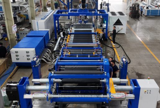
JWELL Machinery’s intelligent TPO sheet production line with multi-component auto-weighing and fully automatic winding delivers high-performance sheets for building waterproofing and automotive interiors.
JWELL Machinery’s intelligent TPO sheet production line with multi-component auto-weighing and fully automatic winding delivers high-performance sheets for building waterproofing and automotive interiors.